Read with Claude
 Read with ChatGPT
Engineering drawings are a language of their own. With standards being defined, a mechanical part drawing from India can be sent to a manufacturer in Germany, and both parties will understand the exact shape, size, and tolerances without verbal explanation, thanks to standards.
Without a shared language, each designer, manufacturer, or engineer could interpret a drawing or blueprint differently one might read a bolt as 10 mm, another as 10 cm, and third ignores a critical tolerance altogether, creating problems in quality and manufacturing.
Basically, standards act like grammar and vocabulary rules for this technical language.
Making Drawings Ready for AI
AI can be used to process engineering drawings using Optical Character Recognition (OCR) and layout analysis to extract information such as dimensions, part names, materials, and tolerances. For this to work effectively, the model needs to understand how these elements are represented according to the drawing standards being followed, whether ISO, ANSI, or others.
Recognizing line types, view conventions, or title block placements is not arbitrary. Each standard dictates its own structure, which determines how data is presented on the drawing sheet. Understanding these standards allows AI models to:
- Segment drawings into logical regions (title block, BOM, views, annotations).
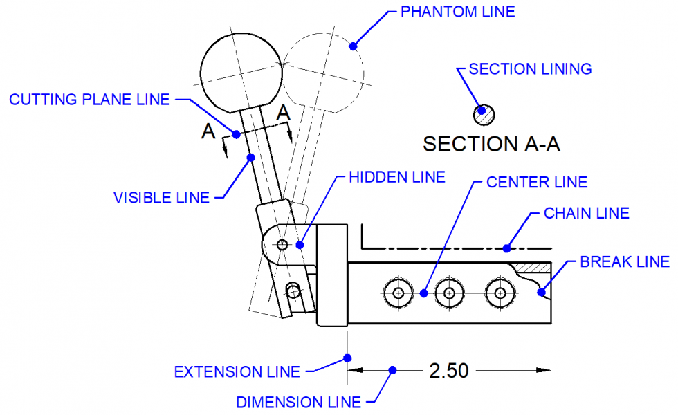
- Detect and classify line types (visible, hidden, center, phantom).
- Identify dimension formats and interpret tolerances accurately.
- Distinguish text areas and lettering standards to enhance OCR accuracy.
- Locate and link Bill of Materials (BOM) tables with referenced callouts.
In this article, we will explore the ISO and ANSI engineering drawing standards and understand their key sub-standards along with the necessary details. This will help us in layout understanding and structural breakdown as we fine-tune our model to perform better with engineering drawing data extraction.
ISO Standards: The Global Framework
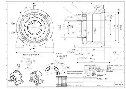
ISO stands for the International Organization for Standardization, helps maintain global standards across industries. In engineering drawing, ISO standards ensure consistency, clarity, and universal understanding of technical drawings, regardless of country or company.
Key ISO standards for engineering drawings:
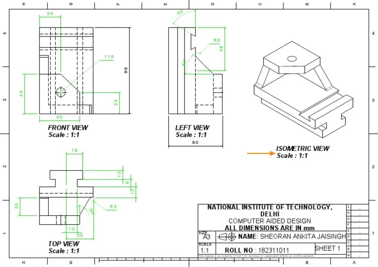
ISO 128
Establishes the general principles for how to present objects graphically on a technical drawing. It is divided into multiple parts that cover aspects like lines, views, and sections.
- Lines: Types of lines (solid, dashed, chain, etc.) and what they mean
- Views: Different views of an object (front, top, side, sectional views etc.)
- Projections: Methods for projecting 3D objects on 2D paper\
- First-angle\
- Third-angle projection
- Symbols: Standard symbols for welding, surface finish, electrical components.
ISO 129
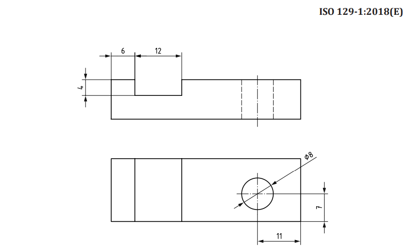
Provides rules for dimensioning and tolerancing.
On the dimension line: A dimensional value and its tolerance are placed on the dimension line, usually above and centered.
- Thin continuous lines for extensions.
- Arrowheads for dimension lines (filled triangle, open, or slanted).
- Keep numbers readable, usually minimum 2.5 mm height.
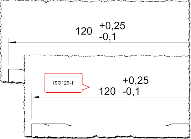
Tolerance are placed next to the dimension it applies
General tolerances
- General tolerances are noted in the title block as Unless otherwise specified..
- Refer ISO 2768, which includes markings like f, m, c, v and note it in the title block.
Tolerances based on geometric specification
- Refer to ISO 14405 for interpretations. Either limit deviations or tolerance symbols are placed next to the dimension. Example: 50 ± 0.1 or 50 +0.1/-0.2
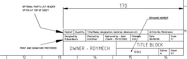
ISO 7200
Defines the data fields to be used in title blocks and document headers. Minimal mandatory fields are used to maximize drawing space.
### ISO 5457
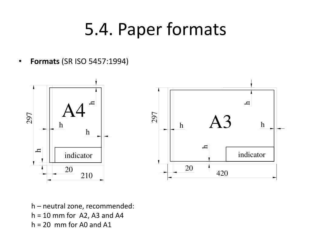
Specifies the sizes and layout of drawing sheets, such as the common A-series sizes (A0, A1, A2, etc.).
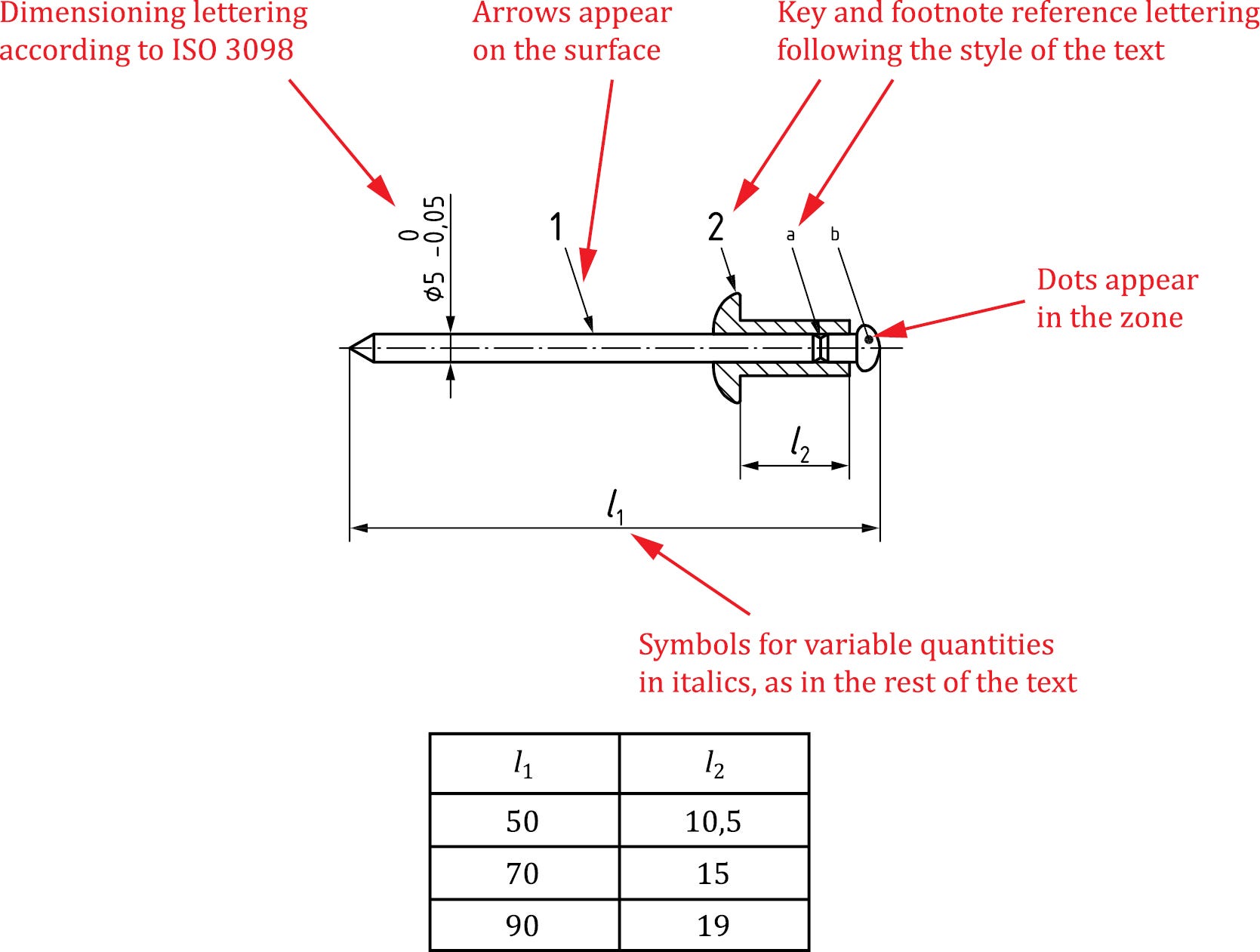
ISO 3098
Specifies the requirements for lettering, including character shape and size, for technical drawings. Consistent lettering avoids misinterpretation of numbers and notes. Example, mistaking 0 for O or 1 for I ensuring technical clarity.
- Defines character shapes, sizes, spacing, and line thickness.
- Uses upright or italic lettering styles.
- Minimum text height is typically around 2.5 mm for general use and larger for titles or headings).
- Letters are written in Gothic sans-serif style, no decorative elements.
- Helps maintain readability when drawings are reduced or printed at different scales.
### ISO 7573: BOM/Part list
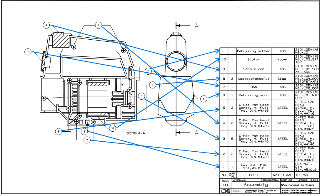
Defines how to create and format a Bill of Materials (BOM) or parts list that accompanies a technical drawing or assembly.
- Specifies structure and layout of the parts list (columns, headers, order).
- Common columns: Item number, Part name, Quantity, Material, Drawing number, Remarks.
- Explains linking methods between item numbers in the drawing and BOM table.
- BOM is located either above or adjacent to the title block. Can be placed on the same sheet or on a separate page.
### ISO 5455
Covers the scales to be used in technical drawings.
Scale is the ratio between size of the drawing and the actual size of the object. Always in ratio form: 1:2, 5:1 and strictly defined. Unit system as millimeters.
ISO 5455:1979 specifies three main types of scales for technical drawings:
- Enlargement scales (2:1)
- Full size scales (1:1) and
- Reduction scales (1:2)
Note: The scale will be loacted near the title block or near the drawing views as Scale: 1:2. Units are assumed as per ISO usually mm.
---
ANSI Standards: U.S. and Custom Applications
### ANSI Y14.2
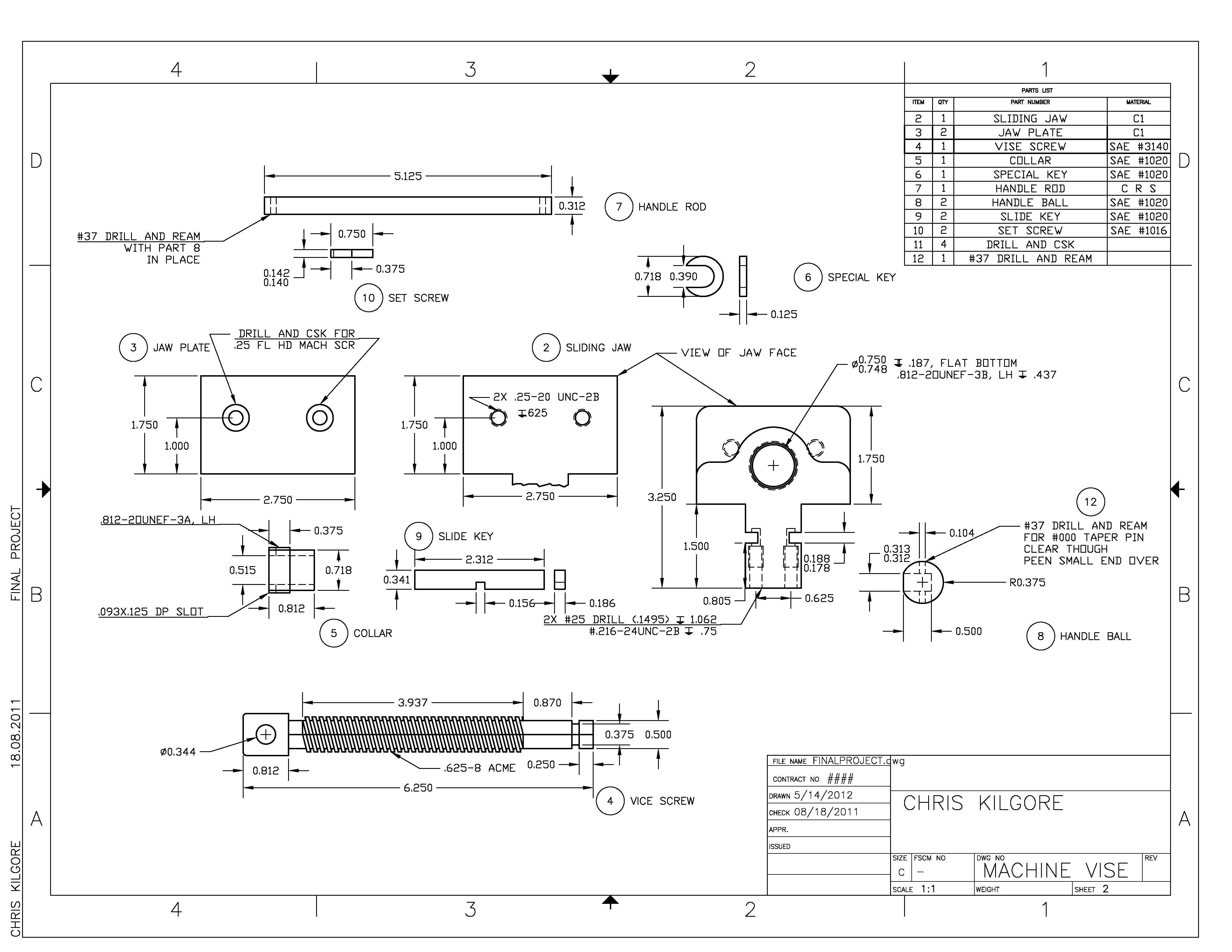
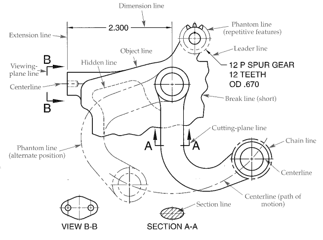
Defines line types (visible, hidden, center, phantom) and lettering with uppercase Gothic sans-serif, single-stroke, standard height and spacing.
Mainly used in U.S. drawings, often in inches. Does not allow lowercase letters, and text proportions do not vary.
### ANSI Y14.5:
Basic rules for dimensioning framework integrated with GD&T.
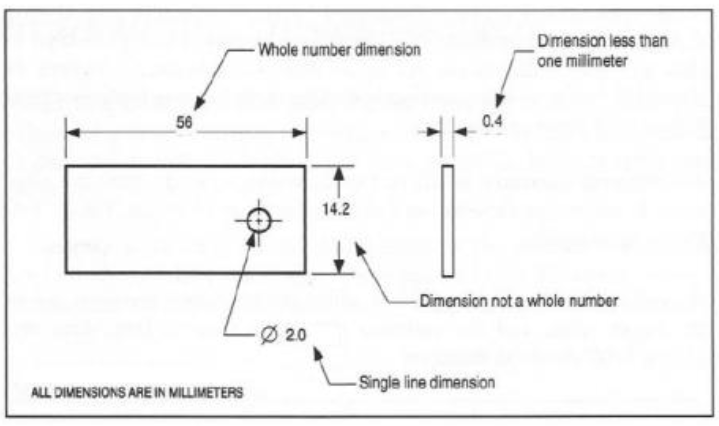
On the dimension line: A dimensional value and its tolerance are placed between the dimension line and centered.
- Thin continuous lines for extensions.
- Filled solid triangles (most common) or slanted/outline arrows.
- Minimum readable height usually 3 mm (varies by company standard).
Tolerance are placed next to the dimension it applies
**1. Limit Tolerances
**Specifies max and min allowed values directly: 50.0 +0.1/-0.2
This means:
- The nominal size = 50.0 mm
- The maximum size = 50.1 mm
- The minimum size = 49.8 mm
Critical features like fits, shafts, or holes where control of size is essential for function or assembly.
**2. General tolerances
**Applied when no specific tolerance is indicated. Defined in title block as “Unless otherwise specified, tolerances are ±X.”
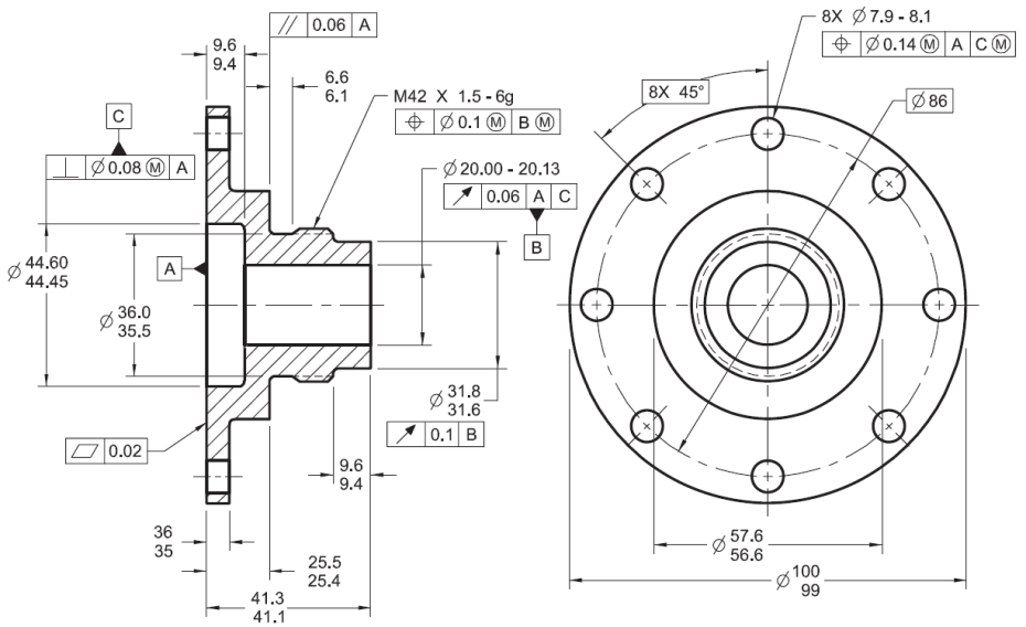
**3. Geometric Tolerances (GD&T):
**Dimension of a part written as say hole diameter = 10 ± 0.1. This controls size, the hole must be between 9.9 mm and 10.1 mm. But what if the hole is slightly off-center, or tilted, or not perfectly round.
That is where feature control frames are used to control form, orientation, location, and profile, not just size.
- Often used for holes, shafts, mating surfaces, and assemblies.
- Basic dimensions (in rectangles) indicate the ideal size/location; FCF indicates allowable deviation.
ANSI Y14.1 / Y14.24
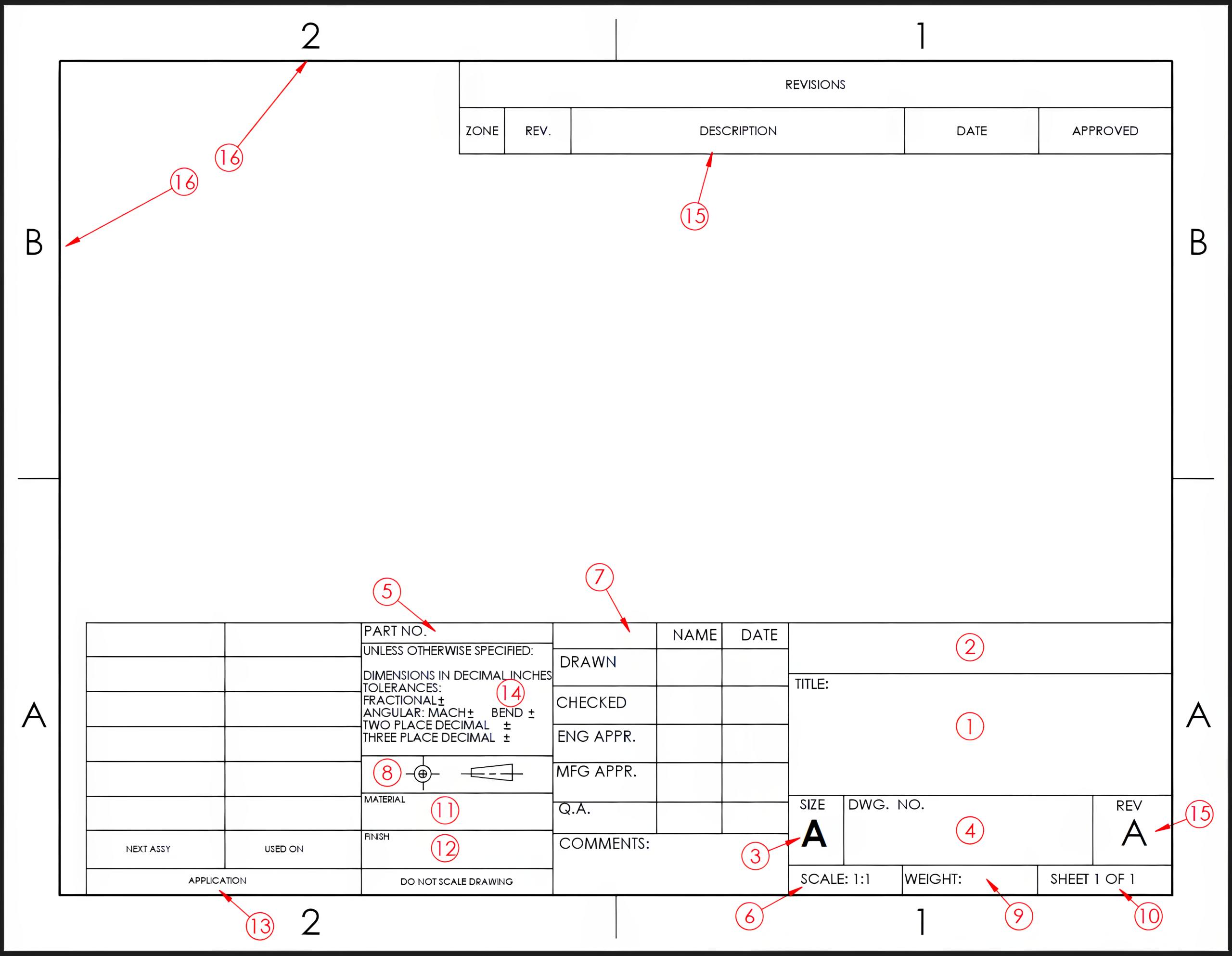
Specifies title block format and required information. Defines the specific location and following key content of a title block on a drawing sheet:
- Drawing title
- Drawing number
- Scale
- Author/Designer
- Date
- Revision history
- May include the project name, sheet number, weight of the item, and legal signatures.
 ### ANSI Y14.1
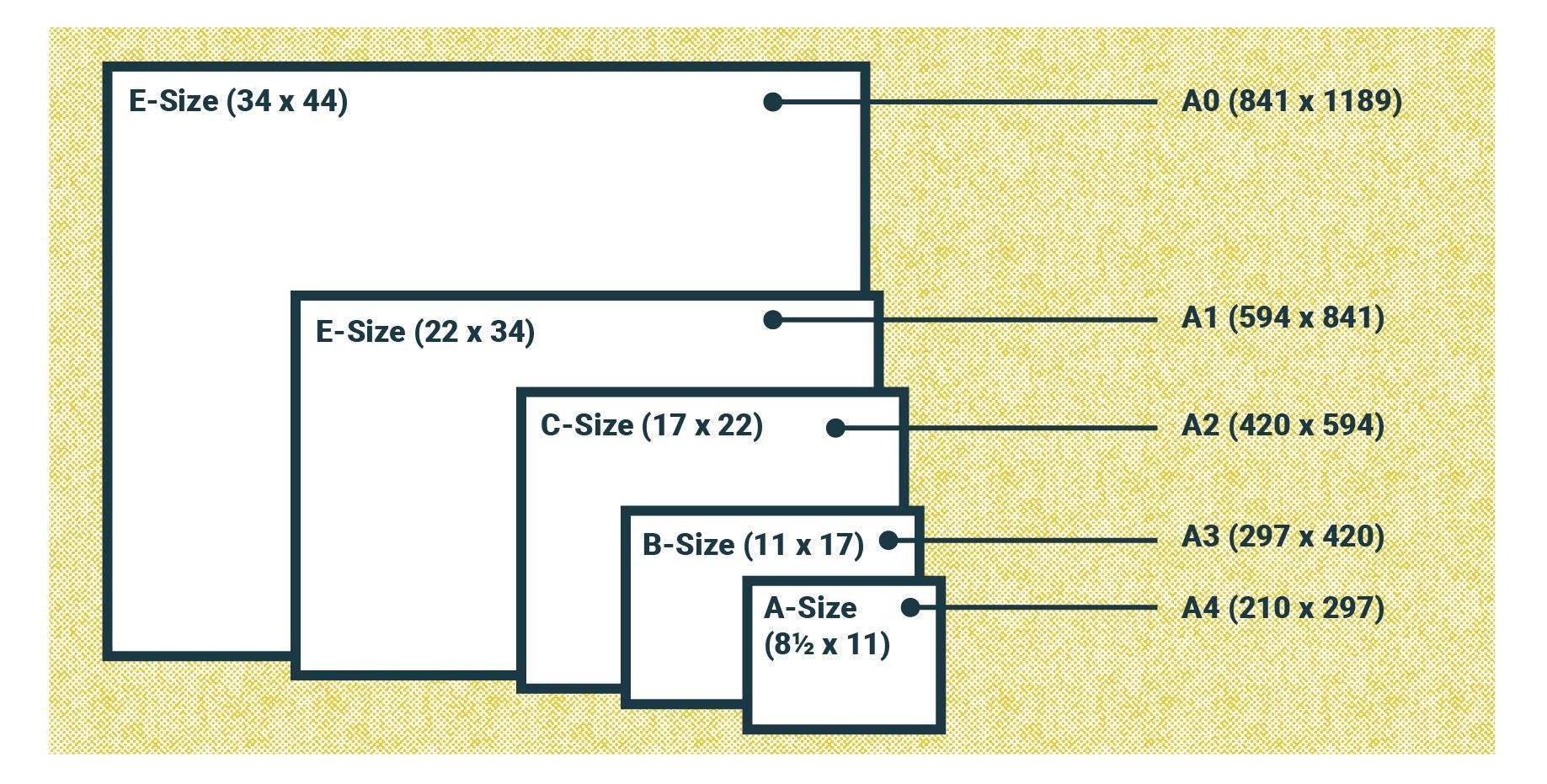
Sizes and layout of drawing sheets. Defines U.S. sheet sizes (A–E) and border margins.
- Defines standard U.S. sheet sizes: A (smallest) to E (largest).
- Specifies border and margin sizes for title blocks, notes, and content.
- Ensures drawing content does not touch sheet edges.
- Left margin is slightly larger for binding. Other margins(top,bottom,right) are uniform.
### ANSI Y14.2
Lettering, including character shape and size
 Lettering & character shape and size
- Uses upright, single-stroke letters in Gothic (sans-serif) style.
- Letters are uppercase, no decorative elements.
- Minimum text height is usually 3 mm for general notes.
ANSI Y14.34
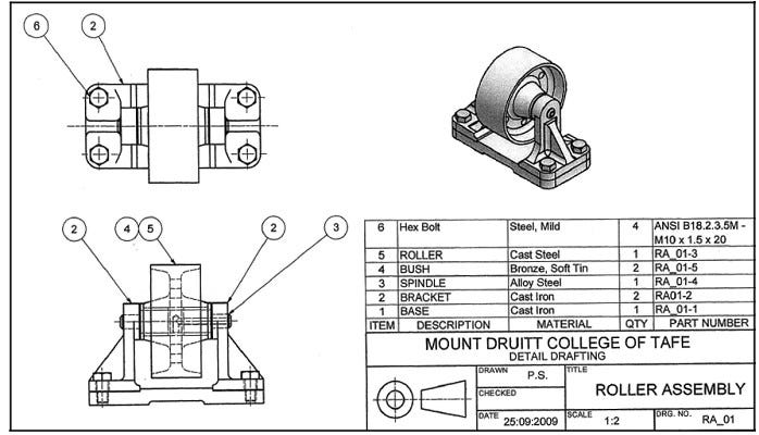
Defines how to create table listing with all parts
Location:
- Directly aside the drawing & above title block.
- On a separate sheet and referenced to the drawing
Reading Direction: Bottom to top, Item 1 is at the bottom, last item at top this allows adding items without reformatting.
Required Columns:
- Item Number: Sequential number (1, 2, 3…) matching balloon callouts on drawing
- Part Number: Unique identifier for each component
- Description/Part Name: What the part is called
- Quantity: How many quantity needed per assembly
Optional Columns (commonly included):
- Material specification
- Size or dimensions
- Weight
- Notes or references
ANSI BOMs may be less strict in format mostly company specific style are used.
ANSI Y14.1 & Y14.3 - Scale Requirements
Indicate and use scales on engineering drawings. Shows the relationship between drawing size and actual part size. Specified as “FULL SIZE”, “HALF SIZE”, or as 1:2 ratios. Flexible, not strictly defined. Unit system as inches
Scale Indication:
- Must be shown in title block (Block H)
- View-Specific Scales: Individual views can have different scales, noted below the view (overrides title block scale for that view).
Common Scales:
- Enlargement scales -Double Size (2:1)
- Full size scales -(FULL SIZE /1:1)
- Reduction scales -(HALF SIZE /1:2)
Special Cases:
- NONE: When drawing has no specific scale
- NTS (Not To Scale): When drawing is schematic or diagrammatic
Bridging Human and Machine Understanding
Engineering drawing standards are more than documentation rules, they are the foundation of how design intent is communicated. As we bring AI into this workflow, these same standards become the bridge between visual understanding and data intelligence.
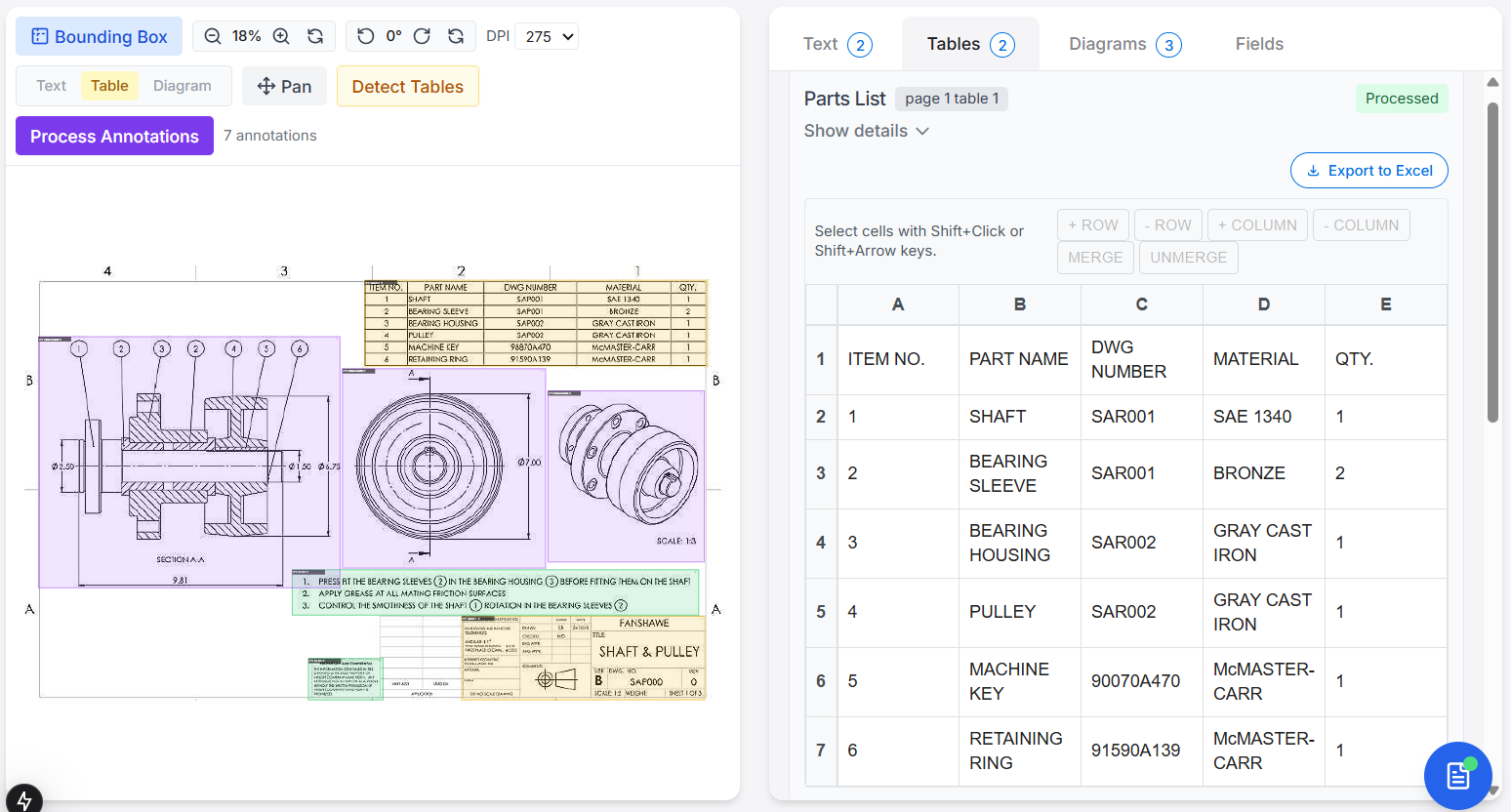
At Coffee, we are building Adeos, a data extraction tool that applies this structured understanding to make engineering drawings machine-readable.
By embedding standard-specific logic into its pipeline, Adeos can:
- Automatically detect title blocks, BOM tables, and scales.
- Recognize and categorize drawing components.
- Extract dimensions and tolerances with unit-aware precision.
- Maintain accuracy across different formats and drawing practices.
In short, engineering standards make intelligent extraction possible.
Conclusion
Engineering drawing standards ensure that designs are clear, accurate, and universally understandable. They provide consistent rules for dimensions, tolerances, lines, views, and lettering etc. reducing errors during manufacturing and assembly.
For AI systems like Adeos, they are the foundation for layout understanding, OCR accuracy, and structural consistency. In short, standards bridge human understanding and automated processing, making engineering work more efficient and error-free.
At Coffee, we are working on Adeos, a data extraction tool that can be used to extract key information from engineering drawings with this exact pipeline in place. If you are interested to learn more, reach out to us.